WEEK
THIRTEEN
Networking and Communication
Task for this Week
Group Assignment
Send a message between two projectsIndividual Assignment
Design, build, and connect wired or wireless node(s) with network or bus addressesGroup assignement
So for the group assignment we have to send the message between two microcontroller devices. So Firstly me an dmy team mate designe the board and then we connect a temperature sensor with one microcontroller and and we displat this temperature in other microcontroller.Click here to know more about group assignment.
Individual Assignment
Before the assignment lets have a look basic about Networking and Communication. We are all living in era of network. We all have lots of network signal aroundus. There is a time when we sent letter but in now days the technology change lots of thing.
Transmission
The mode Transfer of data from one device to another or between two device. Transmission mode is also called the directional mode because it tell about thedestination point to the data . in other word we can say that it contet the address of data.
There are Three type of Transmission Mode-
1. Simplex Mode
2. Half Duplex Mode
3. Full Duplex Mode
Simplex Mode
In this mode of transmission we can the data only in one direction. We did not get the data from receiver side. For example keyboard, Radio Transmission.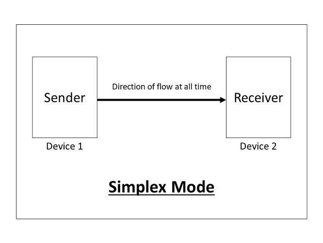
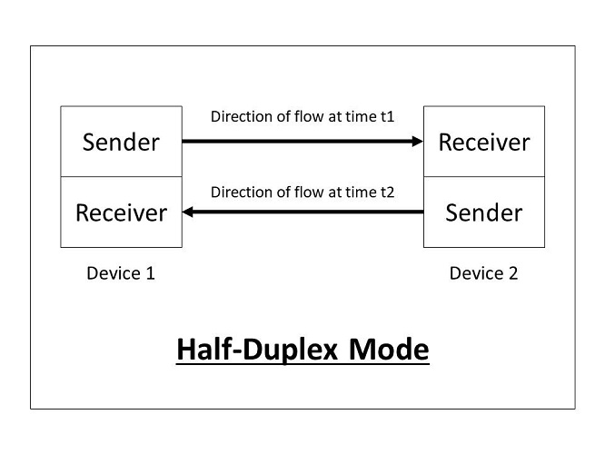
Half Duplex Mode
In this mode of transmission we send the data and receieve the data but not at the same time . At the time of data sending we did not receive the data from thatdevice. for example - walki talki.
Full duplex Mode
In the mode of transmission, we able to send and receive the data at same time . For example our Mobile phone. when we talk we send and receive the dta at a same time.Types of Data
There is two type of data we transmit or receive in our devices.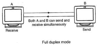
1.Digital Data
The digital data is sen in the form of 1 and 0.
2.Analog data
In analog, data is tranmitted in different pulses and it changes continously
Data Transmission
Data transmission is the transmission of data between two devices. Every device have a sender and receiver. one device send the data by sender and another device
receive the data trough receiver. and then receiver device send the data by sender and another device receive the data.
In analog, data is tranmitted in different pulses and it changes continously
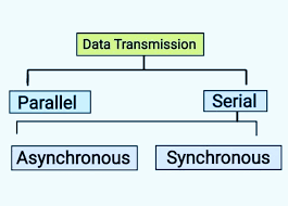
Digital Data Transmission
Digital data transmit in two ways-1.Serial Data transmission
In serial data transmission we send the data one after another in the form of bits by using a single link. this type of transmission used where we have to transmitthe data for long distance. the size of data also low in this. In this transmission the rate of data transfer is slow because we use only single link.
This type of transmission is cost effective. in this we use full duplex transmission mode.
There is a two type of Serial data transmission-
1.Synchronous
2.Asynchronous
Synchronous
In synchronous data transmission, there is a clock which tell the receiver about the data sent and tell the sender about the data is received. And this clock manageall this transmission.
Asynchronous
In ashynchronous there is no external clock. So we put 0 and 1 at end and start of the bit. When recevier receive 0 first it identify the bit is started and at the enddetected 1 means the bit is over.
parallel Data transmission
In parallel data transmission their multi link by which data transfer occure. In this the rate of data transmission is fast when we compared it with serial datatransmission. But when the any link break it is difficult to identify. It is used for the short distance data transmision
This data transmission method use half duplex mode
OSI layer
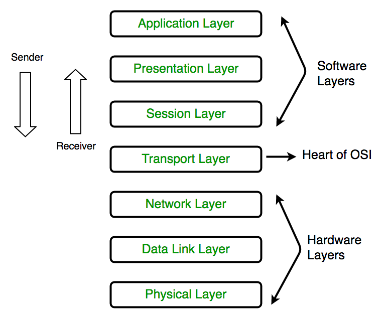
There is time if we have window system then we able to send the information to the window system only. We did not able to sent the message to the different operating
sytem. To overcome this problem There is new Tecknique invented which divided in different layer and caller OSI model. The full form of OSI is Open System Interconnection
This model have 7 different layer, Each layer perform specific task. This model is able to send the data between any two devices.
The layers is -
1.Application Layer
This is the first Layer of OSI model and it show the message we sent or we received on system window. For example Chrome2.Presentation Layer
This is the second Layer OSI model. It take the data from application layer and covert this data into machine language or binary form at sender side. At receiverside it collect the data from session layer which is in binary form and convert this data into readable form
3.Session layer
This layer collect the converted data from presentation layer and it ensure that the data will sent to the authorised system and make a secure connection between them4.Transport Layer
This layer perform the segmentation of the data. It covert the data into small packet and provide the ackowldge of the data is sent successfully. If due to anyerror data is not sent so it send again the data.
5.Network Layer
This layer is responsible for to select shortest distance link in many link. It also place a IP address to the file by which data transmit at particular systemby using IP address.
6. Data link Layer
This layer is responsible for the delivery of data error less. It create the data frame and set the mac adress of receiver to each frame.7.Physical Layer
This is the last layer of OSI Model. It is responsible the actual physical connection. it sending the data in the form of bits. It also have a extranal clock by whichit synchronize the data.
XIAO ESP32 C3
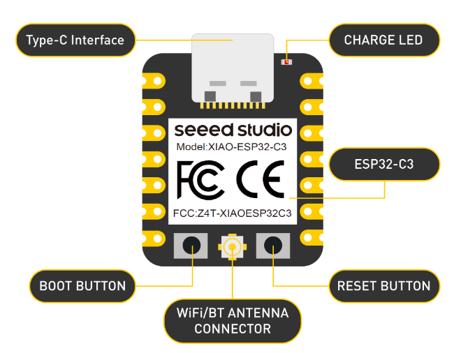
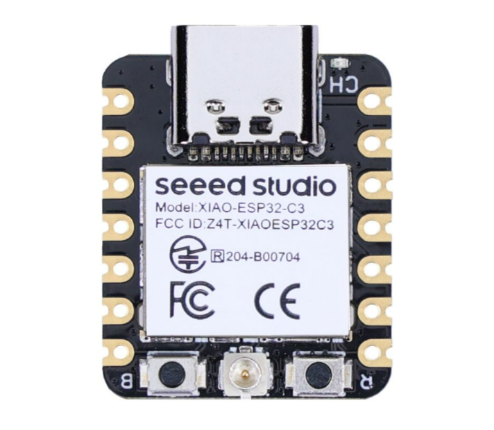
This time I used a Xiao Esp32c3 board. This is the tiny board and its size is 21*17.5mm. This xiao board come with integrated ESP32 C3 chip which operate at 160MHz.
This intigrated chip have 2.4 GHz WIFI system and bluetooth 5.0. It has 400 kb of SRAM and 4 mb of flash memory . The chip required the voltage of 3.3v@200mA. But we
can give the 5v supply. It can work in -40C to 85 C temperature range.
Pin configuration-
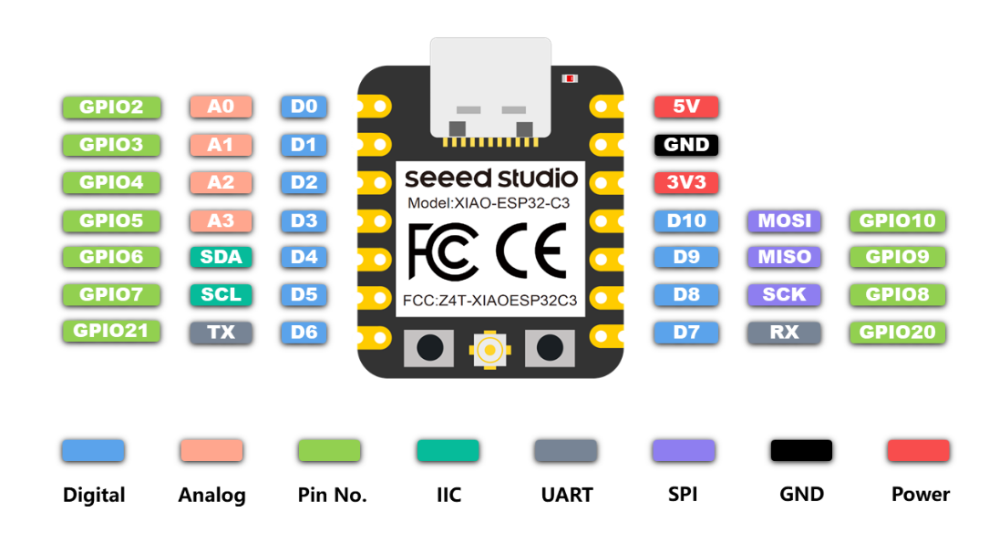
1.Universal asynchronous receiver-transmitter(UART) - 1
2.I2C- 1
3.IIS - 1
4.SPI - 1
5. GPIO -11
6. ADC - 4
It also have a reset and boot button in it.
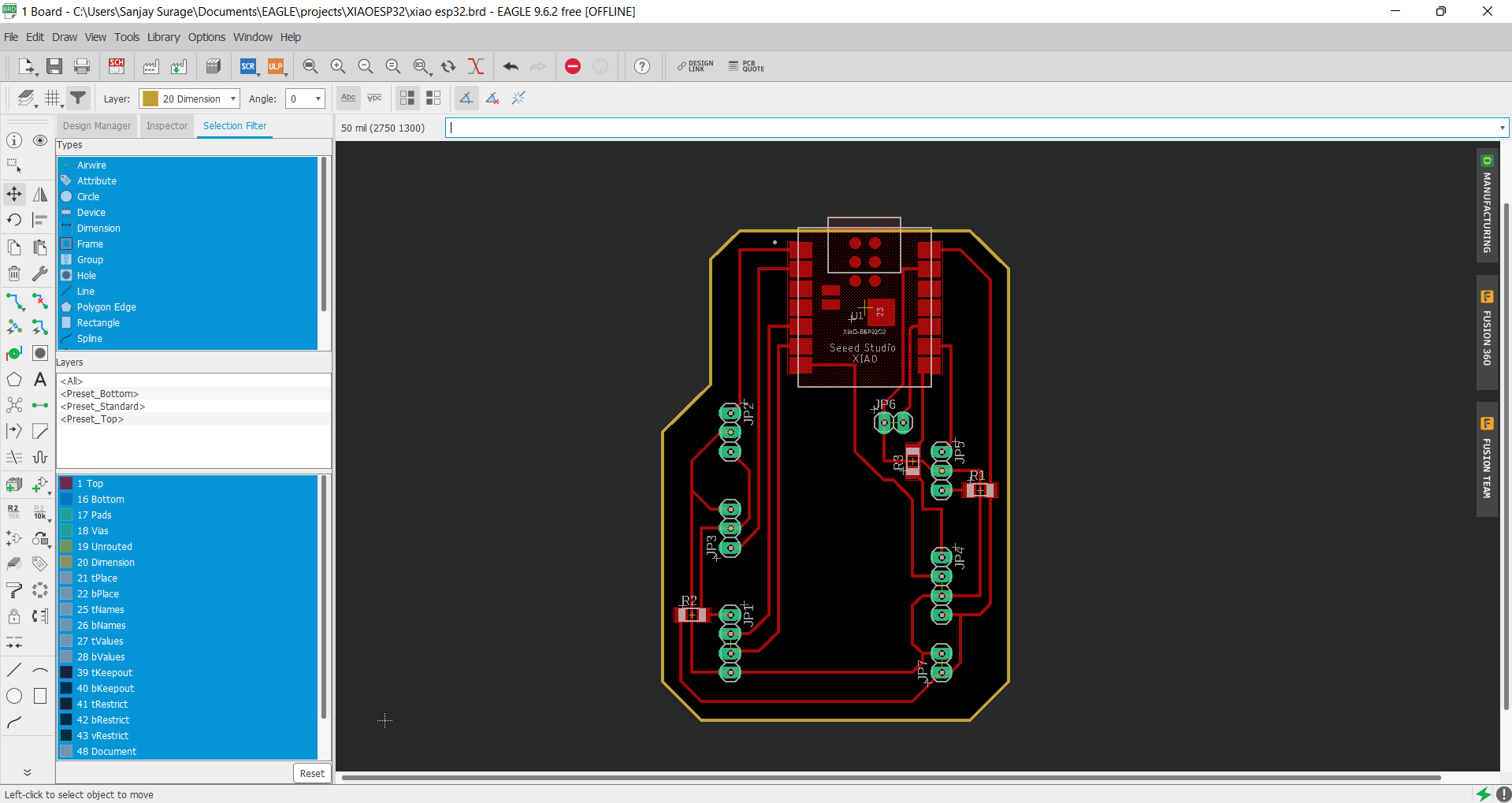
Board Design
I designed the board by using eagle. I choose the pinout according to my final project. Firstly Installed Xiao board library to yhe eagle then select Xiao esp32 board
then choose three pin header, two pin header, four pin header and connect them.
I give Rx, Tx, SDA, SCL and VCC Gnd. and arrange them properly. I connect GPIO2 and GPIO3 pin to the three pin header. this two pin can be used as anolag and digital.
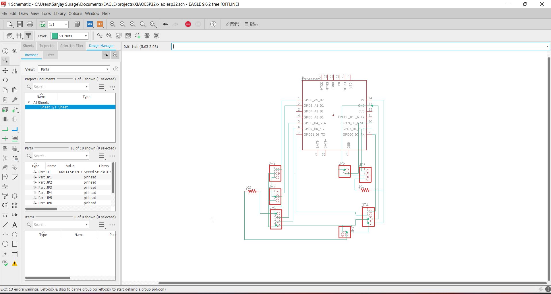
Now GPIO6 and GPIO7 is SDA and SCL pin so i connect them with four pin heasr along with VCC and GND supply. I also choose a 0 ohm resistor to cross the GND wire.
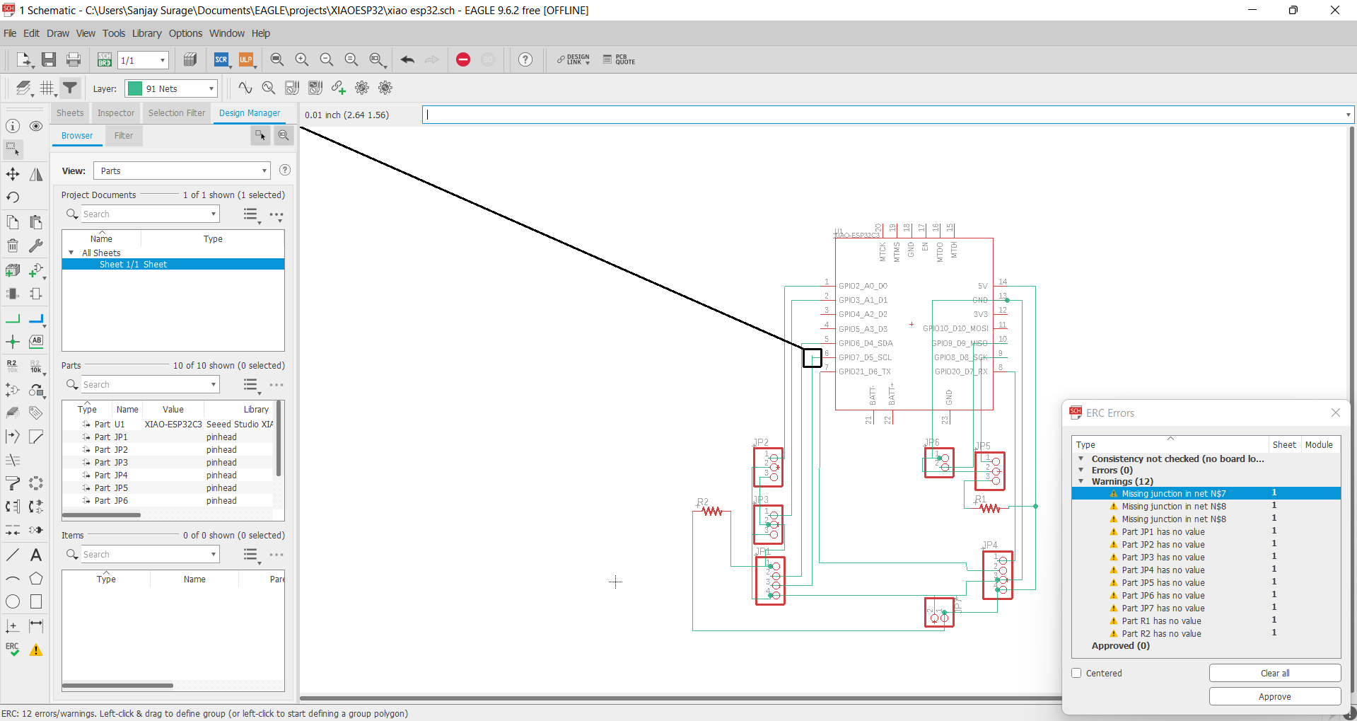
Then I choose GPIO9 With Gnd for LED Indicator. GPIO8 pin used for three pin header connect digital device. Then at last I connect Rx and Tx pin to the four pin header
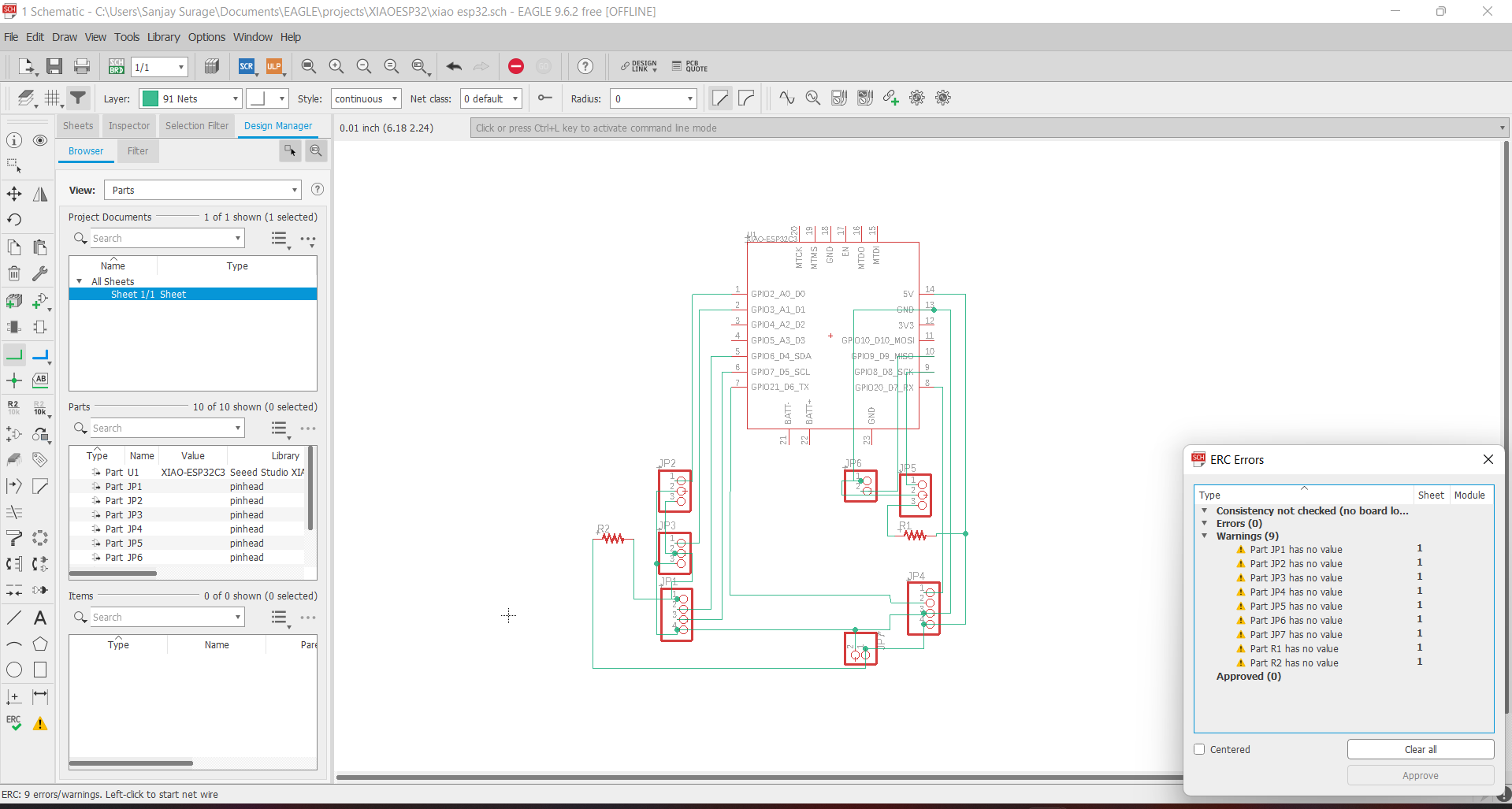
Then I switch to the board design and arrange according my board and export them as png file.
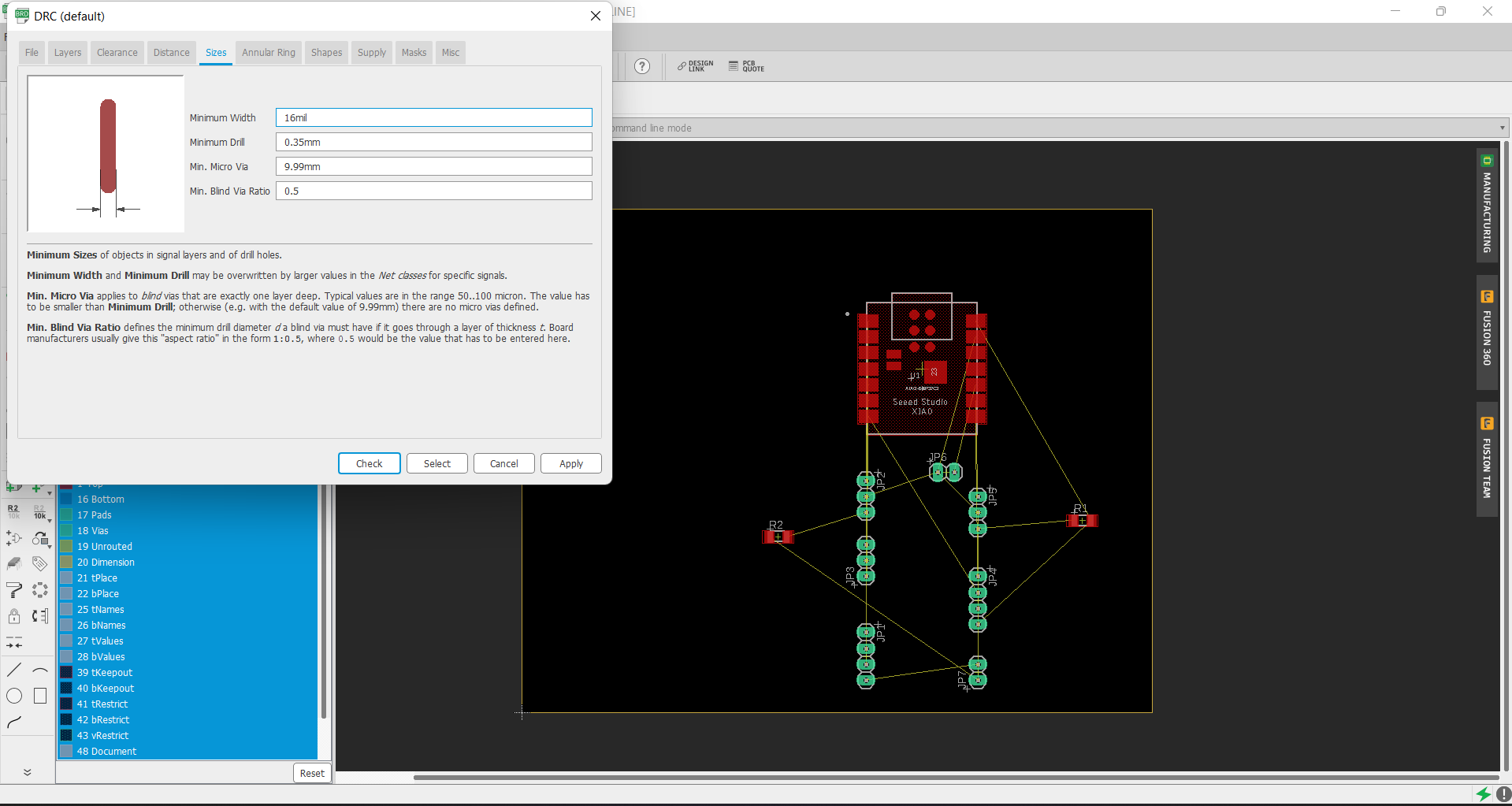
I generated the tool path for the board by using MODs CE platform and then download it.
For the milling I choosed SRM 20 and mill the board properly
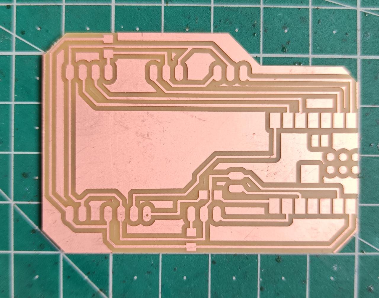
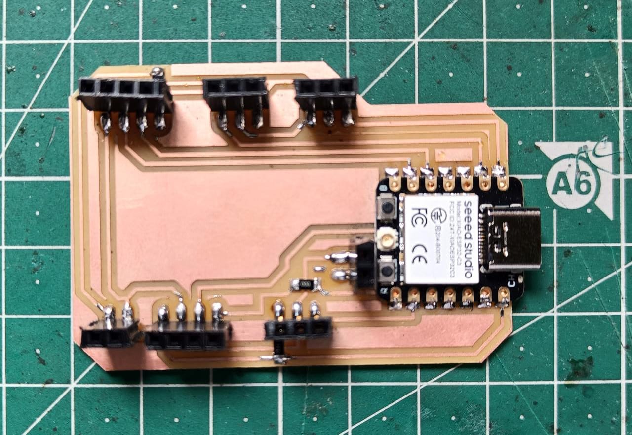
Now I soldered all the component properly and then Board is ready to use.
Led Blink via BLUETOOTH
Bluetooth is technique in which send the signal by using radio frequency. It has short range connectivity. It use a bandwidth of 2.4 GHz frequency to Transmit and
communication data.
Working Mechanism
When we connect bluetooth to any bluetooth device, device follow this process-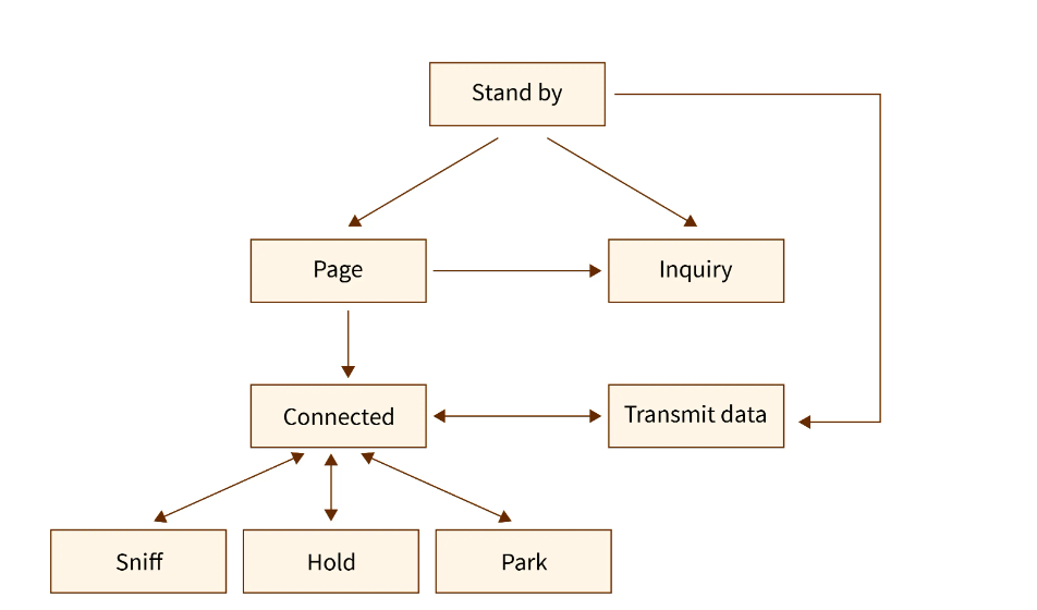
First process is Inquiry, In this it detect the nearby bluetooth device. If any device found then inquiry process end. When we detect device so one device
do inquiry and another device is in scan mode. Then after connection the the bluetooth enter in page state. After successfully connection the bluetooth have one
of them process which is given below-
1.Active mode- In this mode device transfer the data betwee two connected device.
2.Hold Mode- This mode restar the data transfer.
3. sniff- In this mode one device send the data and one device receive the data. in this there is only one way communication occure.
4.Park mode- In this mode the device become inactive.
By using this I blink two leds by bluetooth control system. I connect two leds on my pcb and upload the bluetooth code in it and Download the "nRF Connect" app
and install it in my phone then I connect the this application to the Board. And send the value to the board.
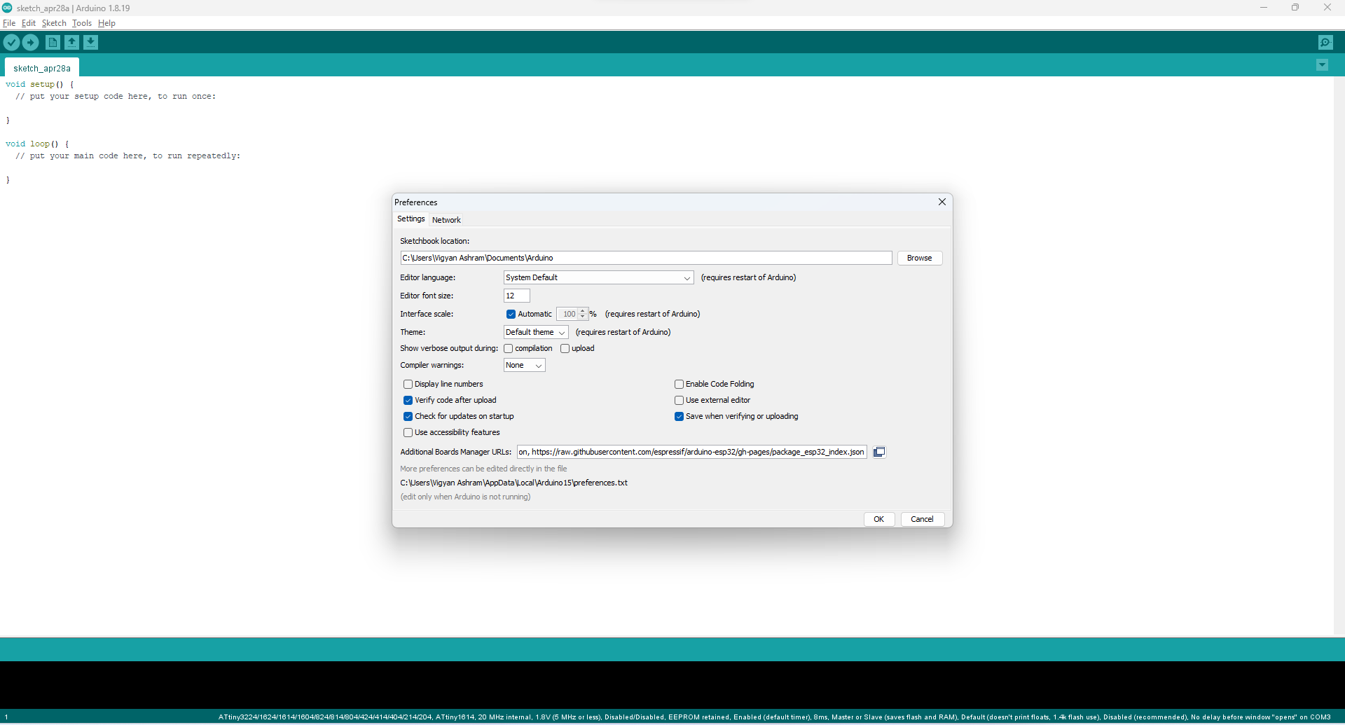
Now firstly we have to install the board into arduino ide. For this follow the step-
File >> Preference >> paste the link which is given below-
"https://raw.githubusercontent.com/espressif/arduino-esp32/gh-pages/package_esp32_index.json"
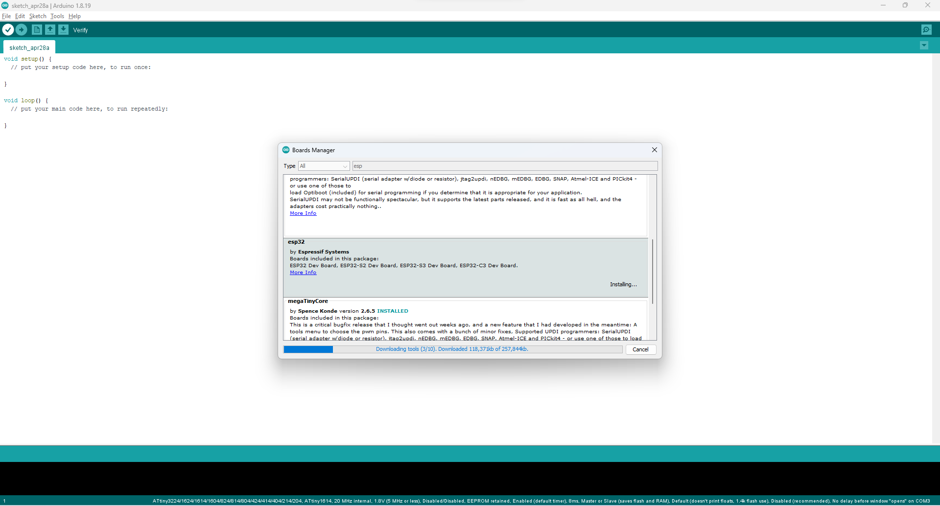
After this go to board manager install this library-
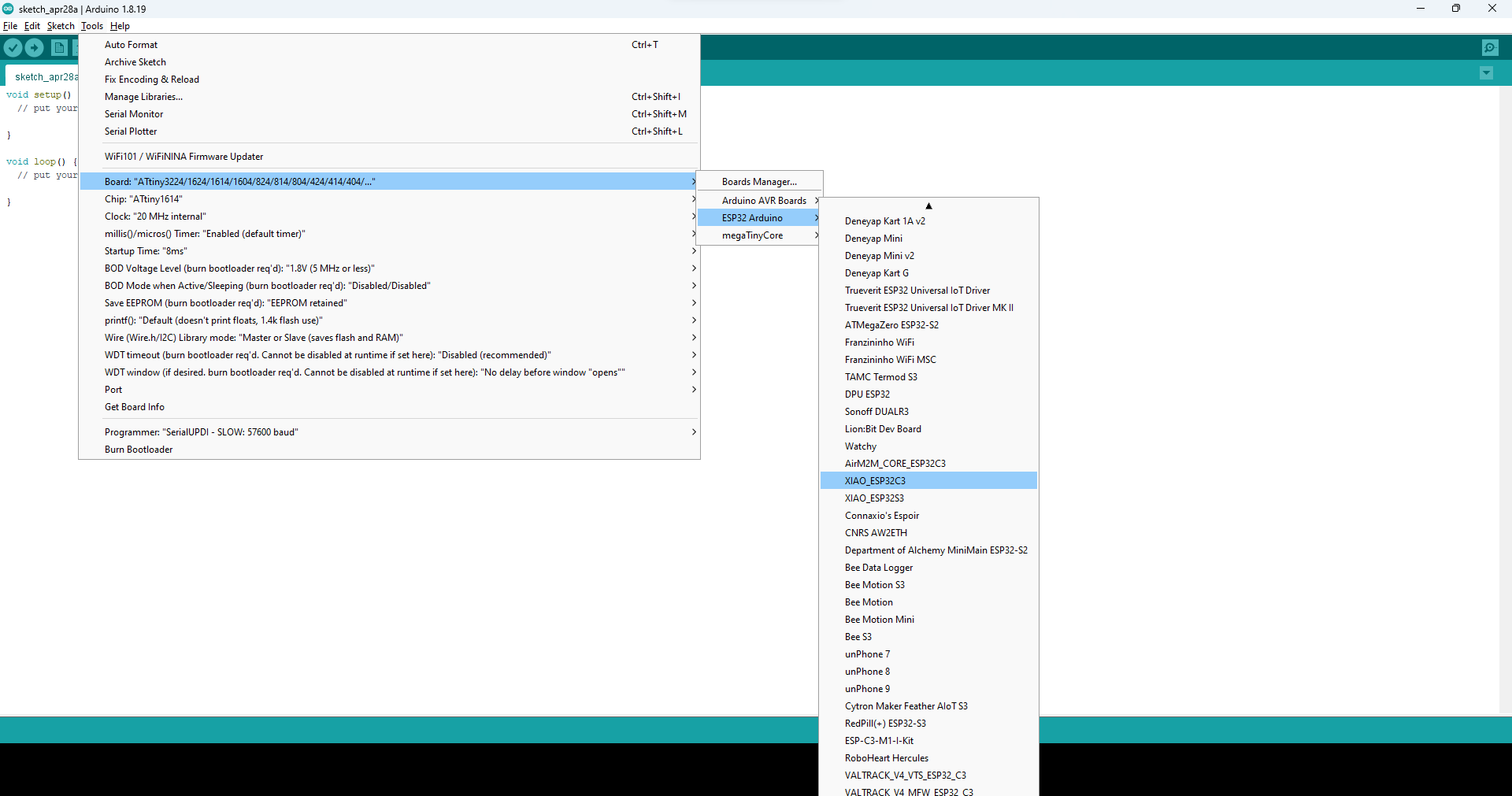
Then select the board type and select port and then upload the following code.
Code
Code compiling and uploading
Result
Motor control by IP address
Internet protocol is a set of rules, which help to data packet to travel theire proper address. At the time of data transfer, Data is conerted into small pieces called packets. we attache the address on each packet by which they will reached the proper destination point. At the time of transferring the packet , they follow transport protocol. IP address is a set of four number and each number have a range from 0 to 255. After this I tried to do motor on and off, So for this I connect my board to the wifi and connect. When a system connect to the internet it have a IP addressReference and credit
Now here I am controlling the motor with Ip address. So I connected the my laptop with same wifi which I mentioned in code and then switch on and off the motor by IP address.
Code-
Code compiling and uploading
Result videos
Learning outcomes
-I learned about the new Xiao board-I learned about how the network work
-I learned about about wireless data transmission techniques.
Download the all original file
Download FileDownload the code file